|
|
Perspective and Orthogonal Views Understanding the two view types |
Perspective and Orthogonal Views

Changing Modes
You can change your current view mode using theViewribbon'sPerspectivetoggle.
What is Meant by 'Perspective' and 'Orthogonal'?
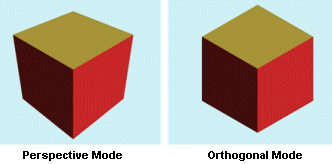
A perspective view implies that the view emulates a real-world panoramic view of the displayed data. Simply put, a perspective view provides a display of a three-dimensional image that portrays height, width, and depth. In the 3D window, a perspective view displays the expected foreshortening affect indicating a virtual 'distance' away from the viewpoint (the 'camera').Two characteristic features of perspective are:
-
objects are drawn smaller as their distance from the camera increases,
- the size of an object's dimensions along the line of sight are relatively shorter than dimensions across the line of sight.
An orthogonal view, also referred to as an 'isometric' view does not indicate depth of field. Instead, geometric data is shown with screen geometry that matches the actual distances associated with the object regardless of how 'far' it is from the camera.
|
|
|
Selecting a View Type
Your application allows you to view 3D scenes using an orthogonal (isometric) or perspective (vanishing point) view. Whereas the latter will give a more accurate rendition of a model in relation to viewing it in a real-world context (with objects 'shrinking into the distance' and all that implies when rotating and moving the viewpoint), an orthogonal non-perspective view does not apply the vanishing point distortion associated with perspective viewing. This can be useful when comparing the dimensions of an object without having to compensate for virtual 'distance' from the viewpoint.
The selection of a view type can impact how data is perceived in the 3D window; a perspective view will provide a sense of depth and immersion, making navigational controls 'feel' more intuitive than say, moving towards and rotating around an orthogonal object. This is because your perception of what is going on is more easily resolved in your brain when the perspective mode is applied - it is a more 'natural' view of a simulated scene. For example, in an orthogonal view, objects that are 'behind' another in the 3D scene will not scale into the distance, enforcing (potentially) a distorted view of object scales in the 3D window.
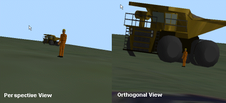
In the example below, two images are shown of the same scene; the image on the left is shown in a perspective view. The perceived depth of field gives both the human and haultruck objects spatial context - you can perceive the virtual distance between the two. However, with an orthogonal perspective, as the illusion of depth is no longer supported (as no vanishing point exists), both objects are shown at their actual scales.

This gives the impression that the haultruck is much closer to the human. In this respect, even though neither view is technically nor computationally incorrect, the left hand image simulates the 'real-world' more effectively due to its support for denoting all three dimensions.
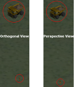
Drawn from a view more directly above the object pair, the effect of the different view modes becomes less apparent. e.g.:

Zooming
Navigating in a parallel projection can feel counter-intuitive to those used to perspective projections. The main reason for this is that as the 'camera' moves forwards, objects in the view do not appear to get closer, as they do not get any bigger. The only indication of forward motion is usually when objects start getting clipped by the view’s front clipping plane. This can be a problem if you are trying to use the free-flight tools, as any subsequent rotations around the camera may be confusing. It is recommended, therefore, you only use the free flight tools for panning whilst in this mode. All other navigation should be done using either preset viewpoints, or Look At mode.
There are 2 primary options for making an object look bigger on the screen: either move the camera closer to it (move forwards), or reduce the field of view (apply zoom). The various zoom controls can be used to zoom in to the data. After selecting a zoom control, a new viewing area is either automatically or manually selected using the left mouse button and dragging the bounding rectangle. Releasing the button will cause the camera to pan so that the rectangle is central, and alter the view width to fit the bounding rectangle. For convenience, the system will also apply a Look At point in the centre of the view, to make subsequent rotations easier. The depth of the Look At point will either be on the first item intercepted in the middle of the view, or an average depth of objects in the view if no item is intercepted. In an orthogonal view, unlike the perspective view, zooming will alter the view width and not move the camera position forward.
|
|
|
Panning
The point to note with 3D scene 'panning' is that although the movement is 'flat', movement results will be dependent on the type of view currently selected.
For example, the following image represents a series of still images of data being 'panned' whilst in a perspective view:

The same data dragged in an orthogonal view would show the following result:

Recommendations
Generally, it is recommended that, for any activities that require the construction or navigation of 3D data for the purpose of producing a presentation, a perspective view will deliver a more immersive experience, and may also be more intuitive to navigate.
|
|
Related Topics |
|
|

